Simple Wooden Phone Stand
This simple wooden phone stand is designed as an approachable first woodworking project. It uses only three wooden parts and introduces several fundamental skills: measuring and marking, making square and angled cuts, drilling pilot holes, countersinking screws, gluing, clamping, sanding, and assembling parts accurately.
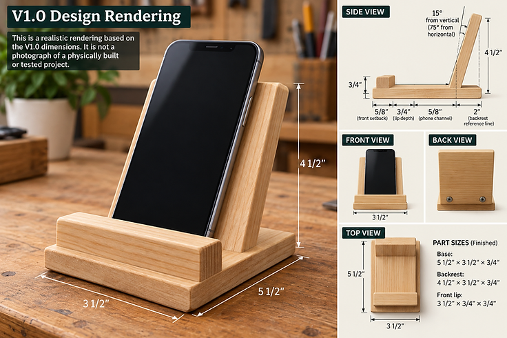
V1.0 design rendering — based on the dimensionally checked Wood Project Lab design. This is not a photograph of a physically built or tested project.
On this page
The finished stand has a 5 1/2" × 3 1/2" footprint, a backrest tilted 15° back from vertical, and a 5/8" phone channel. The design is intended primarily for a smartphone in portrait orientation.
Before You Build
Measure your phone with its normal case installed before assembling the stand.
The V1.0 design provides a 5/8" clear phone channel between the back of the retaining lip and the front reference line of the backrest.
If your phone and case are too thick to fit comfortably within that space, do not assemble the stand according to the standard lip position. The channel should be adjusted for the actual device.
This version does not include a charging-cable opening.
Materials
For the base and backrest:
- Dry, straight 1×4 lumber, with actual dimensions approximately 3/4" × 3 1/2"
- Minimum usable length: approximately 10"
For the retaining lip:
- 3/4" × 3/4" square wood strip, at least 3 1/2" long
Also required:
- Wood glue
- Two #8 × 1 1/2" wood screws
- 120-grit sandpaper
- 180-grit sandpaper
- 220-grit sandpaper
- Optional finish appropriate for the wood and intended indoor use
Pine or poplar can make an approachable first version. Hardwood can also be used.
Tools
You will need an appropriate combination of:
- Tape measure or steel rule
- Pencil
- Combination square
- A reliable method of laying out or cutting a 15° bevel
- Appropriate saw
- Drill/driver
- Drill bit appropriate for the pilot holes
- Countersink bit
- Clamps
- Sanding block or sander
- Eye protection
- Hearing protection when appropriate
- Appropriate respiratory/dust protection
Follow the manufacturer's instructions for every tool you use.
Cut List
| Part | Qty. | Finished Size | Special Cut |
|---|---|---|---|
| Base | 1 | 5 1/2" × 3 1/2" × 3/4" | Square ends |
| Backrest | 1 | 4 1/2" × 3 1/2" × 3/4" | Bottom edge beveled 15° from square |
| Front lip | 1 | 3 1/2" × 3/4" × 3/4" | Square ends |
The 4 1/2" backrest measurement refers to the finished backrest part length established by the V1.0 design. When laying out an angled cut, use the technical drawing as the dimensional reference rather than trying to derive a new dimension from the illustration.
If you're new to working from a parts table, see our guide on how to read a woodworking cut list before laying out these parts.
Technical Drawing
Authoritative technical drawing: Wood Project Lab Simple Wooden Phone Stand V1.0.
The drawing is supplementary. Every dimension it shows is also given in text throughout this page, including the Cut List above and the Dimension Summary below.
Understanding the Layout
There are three important positions measured from the front edge of the base.
5/8" — Front Face of Retaining Lip
The lip begins 5/8" behind the front edge.
1 3/8" — Rear Face of Retaining Lip
Because the lip is 3/4" deep: 5/8" + 3/4" = 1 3/8"
2" — Backrest Front Reference Line
That leaves: 2" − 1 3/8" = 5/8" between the rear of the retaining lip and the backrest reference line. That is the phone channel.
The complete front-to-back dimensional chain is: 5/8" setback + 3/4" lip + 5/8" phone channel = 2" backrest reference line.
Do not measure each dimension independently if you can avoid it. Establish the front edge of the base as your common reference point.
For a broader framework, see our guide on measuring and marking wood accurately before laying out your parts.
Step-by-Step Instructions
Step 1: Inspect and Prepare the Wood
Choose straight, dry stock without major defects in the areas that will become the three components.
If you're using nominal 1×4 lumber, verify its actual dimensions before beginning. The V1.0 plan is based on stock approximately 3/4" thick × 3 1/2" wide.
Don't assume the board's nominal name gives you its actual finished dimensions.
Mark the best faces of the material so you can orient them consistently during assembly.
Step 2: Cut the Base
Measure and mark a 5 1/2" length of the 1×4 material.
Use a square to carry the cut line across the board.
Cut the base to: 5 1/2" × 3 1/2" × 3/4"
The ends should be square.
After cutting, verify that the finished base is 5 1/2" long before using its front edge as the reference for the remaining layout.
Step 3: Cut the Backrest
Prepare another piece of the 1×4 material for the backrest.
Its finished size is: 4 1/2" × 3 1/2" × 3/4"
The bottom edge requires a 15° bevel from square so the backrest can lean 15° rearward while meeting the horizontal base.
This corresponds to the backrest sitting approximately 15° from vertical, or 75° from horizontal. These describe the same orientation.
Use an appropriate tool and setup for the bevel cut. Make sure you understand which direction the bevel must run before cutting: when assembled, the backrest must lean toward the rear of the base, not toward the phone-retaining lip.
If you're uncertain about the orientation, compare the part to the side view in the technical drawing before making the cut.
Do not attempt to hold a small workpiece by hand in an unsafe position simply to produce the angle. Use appropriate workholding and follow the saw manufacturer's instructions.
Step 4: Cut the Front Retaining Lip
Cut the 3/4" square stock to: 3 1/2" long × 3/4" high × 3/4" deep
The ends are square.
The finished lip should span the full 3 1/2" width of the base.
Step 5: Dry-Fit the Three Pieces
Do not apply glue yet.
Place the base flat on the work surface.
Position the retaining lip across the width of the base. Its front face should be 5/8" from the front edge of the base.
Because the lip is 3/4" deep, its rear face should now be: 1 3/8" from the front edge.
Mark the backrest front reference line: 2" from the front edge of the base.
Position the backrest at that reference location with its beveled bottom seated against the base and the backrest leaning toward the rear.
Check the space between the retaining lip and backrest reference. It should be: 5/8"
Step 6: Test the Phone Fit
Before drilling or gluing anything, place the phone—with its normal case installed—in the channel.
This is a fit check, not a final assembly test.
The phone should enter and leave the channel comfortably without needing to be forced between the lip and backrest.
If the phone/case combination is too thick, stop here.
Do not simply force the phone into the standard V1.0 opening. Adjust the lip position to provide the necessary clearance for the actual device before proceeding.
If you change the channel dimension, record that change so subsequent layout is based on your modified design rather than the standard 5/8" specification.
Step 7: Mark the Backrest Position
Once the fit has been confirmed, carefully mark the backrest's location on the base.
The V1.0 front reference is: 2" from the front edge of the base.
Use a square to carry the reference across the 3 1/2" width.
Position the beveled backrest against the base and confirm once more that it leans rearward.
Step 8: Mark the Two Backrest Screw Locations
Turn the base over so you can mark its underside.
The V1.0 backrest uses two #8 × 1 1/2" wood screws driven upward through the base and into the backrest.
Both screw centers are: 2 1/4" from the front edge of the base.
Across the 3 1/2" width, mark the screw centers at: 1" from one side edge, and 2 1/2" from the same side edge.
This gives: 1 1/2" center-to-center spacing, and places each screw center 1" from its nearest side edge.
The two screw-center coordinates, measured from the same front and side reference edges, are therefore:
Screw 1: 2 1/4" from front × 1" from side
Screw 2: 2 1/4" from front × 2 1/2" from side
Double-check these locations before drilling.
Step 9: Drill the Backrest Pilot Holes
With the screw locations marked on the underside of the base, drill the two pilot holes.
Use a pilot-hole diameter appropriate for the #8 screws and the wood species you're using rather than relying on an arbitrary universal pilot-hole size.
Countersink the holes on the underside of the base so the screw heads can finish flush with or slightly below the bottom surface.
This is important because protruding screw heads could prevent the stand from sitting flat and could scratch the surface beneath it.
Step 10: Transfer or Align the Backrest for Assembly
Return the base to its upright position.
Place the backrest at its marked location and confirm: the beveled edge seats properly; the backrest leans toward the rear; its front reference corresponds with the 2" layout line; the phone channel remains correct; the backrest is centered across the 3 1/2" width.
Clamp or otherwise secure the backrest appropriately so it cannot shift during fastening.
Because screw behavior varies with wood species and drilling technique, use appropriate pilot drilling into the backrest as necessary to reduce the risk of splitting and to guide the screws accurately.
Step 11: Attach the Backrest
Once you are satisfied with the dry fit, remove the backrest and apply an appropriate amount of wood glue to the mating surface.
Reposition it precisely. Clamp it securely.
Drive the two #8 × 1 1/2" wood screws from underneath the base into the backrest.
Do not overtighten. The goal is to bring the joint together securely—not crush the wood or strip the screw hole.
Check the backrest before the glue begins to set. It should remain 15° back from vertical and centered across the base.
Remove excess glue according to the adhesive manufacturer's recommendations.
Step 12: Position the Front Lip
Mark or confirm a line: 5/8" from the front edge of the base. This represents the front face of the lip.
Position the 3 1/2" × 3/4" × 3/4" lip across the full width of the base.
Its rear face should end at: 1 3/8" from the front edge.
The standard V1.0 clear space between the rear of the lip and the backrest front reference line is therefore: 5/8".
Dry-fit the phone one more time before gluing the lip.
Step 13: Glue the Front Lip
For V1.0, the standard front-lip attachment is wood glue and clamping.
Apply glue to the mating surface of the lip.
Place it at the established position and clamp it securely without causing it to slide.
Check from both ends to make sure the lip remains square across the width of the base.
Remove excess glue as appropriate.
Allow the adhesive to cure according to its manufacturer's instructions before putting the stand into service.
The V1.0 technical drawing intentionally does not specify screw locations for the front lip. Do not add arbitrary screw locations and present them as part of this plan.
For a full walkthrough of the process, see our guide on wood glue basics.
Step 14: Sand the Stand
Once the glue has cured, sand the project.
A reasonable progression for this project is: 120 → 180 → 220 grit
The amount of sanding required depends on the condition of the lumber and the quality of the cuts.
Pay particular attention to: sharp exposed edges; saw marks; end grain; the top of the retaining lip; areas the phone may contact; glue residue.
Do not aggressively sand away important mating surfaces before assembly merely to reach a particular grit.
The goal is a smooth, comfortable finished object—not sanding for its own sake.
Step 15: Apply a Finish — Optional
The phone stand can be left unfinished or given an appropriate indoor wood finish.
If applying a finish: follow the finish manufacturer's instructions; observe ventilation requirements; follow stated drying and curing times; don't place the phone against a finish that hasn't adequately cured.
Wood species and finish choice can substantially change the appearance of this simple design, making the same plan suitable for inexpensive practice lumber or more decorative hardwood.
Final Inspection
Before using the stand, check:
- Base sits flat.
- No screw heads protrude from the underside.
- Backrest is firmly attached.
- Front lip is firmly attached.
- No sharp edges or splinters remain.
- Phone fits the channel without being forced.
- Phone rests securely against the backrest.
- Stand remains stable with the intended phone installed.
Do not assume that successful fit with one phone means the stand fits every smartphone or case.
V1.0 Dimension Summary
| Feature | V1.0 Dimension |
|---|---|
| Base | 5 1/2" × 3 1/2" × 3/4" |
| Backrest | 4 1/2" × 3 1/2" × 3/4" |
| Front lip | 3 1/2" × 3/4" × 3/4" |
| Backrest lean | 15° from vertical |
| Backrest orientation | 75° from horizontal |
| Lip front face | 5/8" from base front |
| Lip rear face | 1 3/8" from base front |
| Phone channel | 5/8" |
| Backrest front reference | 2" from base front |
| Backrest screw depth coordinate | 2 1/4" from base front |
| Screw #1 width coordinate | 1" from side |
| Screw #2 width coordinate | 2 1/2" from same side |
| Screw spacing | 1 1/2" center-to-center |
| Backrest screws | 2 × #8 × 1 1/2" |
Beginner Tips
Measure From One Reference Edge
Using the front edge of the base for the depth measurements reduces cumulative layout errors.
Dry-Fit Before Gluing
The time to discover that your phone case doesn't fit is before adhesive is applied.
Mark the Front and Back
This makes it much harder to accidentally install the angled backrest in the wrong direction.
Drill Pilot Holes
Small components can split when screws are driven without appropriate preparation.
Don't Chase Perfect Speed
For a first woodworking project, accurate layout and controlled operations matter more than completing it quickly.
Common Mistakes
Installing the Backrest Backward
The backrest should lean toward the rear of the stand.
Confusing 15° and 75°
The backrest is 15° from vertical, which is equivalent to 75° from the horizontal base.
Forgetting the Phone Case
Measure the phone in the configuration you normally use.
Moving the 2" Reference Line Accidentally
The standard V1.0 geometry uses a 5/8" front setback, 3/4" lip, and 5/8" channel, totaling exactly 2".
Using Protruding Screws Underneath
Countersink the backrest screws so the base can sit flat.
Skipping the Dry Fit
Once glue is applied, correcting layout errors becomes much harder.
Safety
Frequently Asked Questions
Will this wooden phone stand fit my phone?
The standard V1.0 design has a 5/8" phone channel. Measure your phone with its normal case installed before assembly. If the device does not fit comfortably within that space, adjust the lip position to provide the clearance you need.
Does the stand work with a phone case?
It may, depending on the total thickness of the phone and case. The design should not be described as fitting every case. Measure the actual device in the configuration you normally use before attaching the retaining lip.
Can I charge my phone while it is in the stand?
V1.0 does not include a charging-cable opening. Do not add an invented charging-slot dimension to this plan. A charging-compatible variation may be developed separately later.
Do I need a table saw to build this phone stand?
No. The project does not inherently require a table saw. Use an appropriate cutting method capable of making the required cuts safely and accurately.
Why is the backrest angle listed as both 15° and 75°?
They describe the same orientation from different references. The backrest leans 15° away from vertical, which places it at 75° relative to the horizontal base.
Why does the plan use a 2" backrest reference line?
The standard front geometry is: 5/8" front setback + 3/4" retaining lip + 5/8" phone channel = 2". Using one front reference edge helps keep the layout internally consistent.
Where do the backrest screws go?
Both screw centers are 2 1/4" from the front edge of the base. Across the 3 1/2" width, the first screw is 1" from one side and the second is 2 1/2" from that same side. That produces 1 1/2" center-to-center spacing.
What type of wood should I use?
Pine or poplar can be practical choices for a first version. Hardwood can also be used. Choose dry, straight material appropriate for the project and consider how the wood behaves when drilling, fastening, sanding, and finishing.
Has Wood Project Lab physically tested this design?
No. This Wood Project Lab design has been developed and dimensionally checked for internal consistency, but it has not been physically prototype-tested. Measure your device before building and make appropriate adjustments for your phone and case.
Where to Go Next
If this is one of your first woodworking projects, return to 25 Easy Woodworking Projects for Beginners. You can also browse the full library of Woodworking Projects.